Universal Integrating Sphere Design Criteria for the Measurement of Optical Material Properties
The optical properties of materials are routinely described in terms of their reflection, transmission and absorption [1]. To measure these key parameters, materials are exposed to optical radiation which is then partially reflected, transmitted or absorbed by the samples. The most common type of equipment for measuring these optical properties is a spectrophotometer. These instruments comprise a light source for sample illumination, a sample holder with measuring geometry for steering the reflected or transmitted radiation and a detector for measuring the radiation. If the light source provides broadband illumination of the sample then a spectrometer, typically array based, will form the detector stage. Alternatively, the sample may be illuminated with monochromatic radiation that is scanned through the wavelength range of interest. In this configuration, single element photodetectors such as photomultiplier tubes and photodiodes are used.
In applications where scattering materials are measured, spectrophotometers incorporate an integrating sphere [2] within the sample measuring geometry. However, most commercial spectrophotometers are rather limited regarding their available space and access for using integrating spheres. For situations where they cannot be used there is a need for universally configurable integrating spheres. Their design must be optimally adapted to the measurement requirements of each optical parameter.
Design Considerations
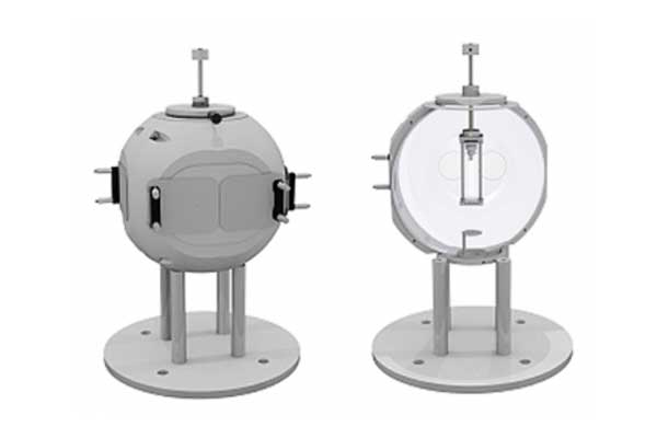
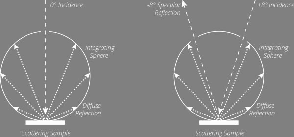
Often the best possible compromise between high optical throughput and sphere size can be achieved with a 150 mm diameter (6 inch) integrating sphere. Their spherical surface area of ca. 71,000 mm² allows a total area of up to 3,500 mm² to be used for application and detector ports, while maintaining the recommended <5% port area to sphere surface ratio. For a universally designed integrating sphere, a 150mm diameter sphere therefore permits five application ports each up to 30 mm in diameter (700 mm²). With these five ports the two measuring geometries 0 / d and 8 / d (with light trap) can be realized.

Picture: 0 / d and 8 / d measuring geometry
The design of the application ports is of crucial importance for the precise measurement of reflection and transmission of scattering samples. Their edges must have a very narrow lip with so-called ‘knife edges’. The radiation scattered by the sample can thereby enter the integrating sphere even at shallow angles of incidence without contact with the side edges of the application port.
Port plugs allow the closure of any unused application ports and port reducers can be used to reduce the size of an application port thereby effectively increasing the sphere’s surface area. It is important that the face of any port reducer lies in the same plane as the sphere’s surface. In addition, this face must be coated as per the coating of the hollow sphere. This is the only way to ensure undisturbed radiation distribution within the integrating sphere.
Measurement Considerations
To measure the reflection and transmission, the samples are attached to the outside of an application port. The required sample holders are ideally designed so that the sample is pressed flat against the area around the port. The contact pressure should be independent of the sample thickness. In addition, it must be possible to combine the sample holders with port reducers and other accessories such as light traps. These are always required when semi-transparent material samples are to be measured with regard to their reflection. In this case the light trap provides a defined black background without any re-reflection.
To measure absorption, material samples are placed inside the integrating sphere. Liquid samples are measured in cuvettes. The sample holders must be adjustable in height and rotatable to position the samples. The sample opening must be closed by the plug of the sample holder. It is important that the sphere side of the plug lies in the plane of the hollow sphere and is coated. Only in this way is the undisturbed radiation distribution in the integrating sphere also ensured in the region of the sample port. If the mounting rod of the sample holder is hollow, additional leads for electrical connection to the samples can be guided into the integrating sphere.
The south pole of the integrating sphere provides a favorable position for the radiation detector. For reflectance and transmission measurements, the detector must be baffled from the application port that holds the sample. For absorption measurements, a baffle must be placed between the detector and the sample in the center of the integrating sphere.
Optical Measurement Solutions for Material Properties
Gigahertz-Optik GmbH offers the UPB-150-ARTA 150 mm integrating sphere with accessories for universal reflection, transmission and absorption measurements. If the applications are limited to reflection and transmission, the model UPB-150-ART offers a lower cost alternative.
References
[1] Tutorial Basics of Light Measurement – 1.8 Reflection, Transmission and Absorption
[2] CIE 130-1998 Practical Methods for the Measurement of Reflectance and Transmittance