Flicker measurement (Temporal Light Artefact) of LED lighting
Content:
3. Flicker measurement using the BTS256-EF
3.2 Measurement accuracy and configuration
4. Flicker measurement using the PFL-200
5. Flicker measurement using the BTS2048-VL
1. Brief description
The widespread introduction of Solid-state lighting (SSL) has required the effects of light flicker to be considered more thoroughly than with previous generation technologies such as magnetic ballast fluorescent lighting. In principle the light output from LEDs follows the current; however the AC main power has to be transferred to DC signals which are needed for the LED itself. Therefore, electronic drive circuitry of LEDs as well as external controllers and dimmers are needed and can readily introduce modulation in the light output in addition to the effects of any mains supply fluctuations and transients. Many LED drivers use pulse-width modulation (PWM) for dimming control which employs high modulation of a single frequency with varying duty cycles. These electronic circuits can contain high frequency components in addition to the typical low frequency oscillations that result from AC mains supply frequencies.
The variation in light output over time from a light source is colloquially referred to as ‘flicker’ and can have both visual and non-visual detrimental effects on the observer. In accordance with CIE TN 006:2016 [12], these effects are more properly referred to collectively as ‘Temporal Light Artefacts’ (TLAs). Three types of visually perceptible TLAs are classified:
- Flicker: perception of visual unsteadiness induced by a light stimulus the luminance or spectral distribution of which fluctuates with time, for a static observer in a static environment.
- Stroboscopic Effect: change in motion perception induced by a light stimulus the luminance or spectral distribution of which fluctuates with time, for a static observer in a non-static environment.
- Phantom Array Effect (Ghosting): change in perceived shape or spatial positions of objects, induced by a light stimulus the luminance or spectral distribution of which fluctuates with time, for a non-static observer in a static environment.
Much research has reported that non‐visual TLAs might also have various physiological and psychological effects such as migraines, seizures, autistic behavior, vertigo, reduced performance, emotional changes among others [1-11]. IEEE 1789:2015 [13] provides a summary of known effects.
The metrics Pst and SVM have recently received a boost in significance. In September 2021, the Eco-design directive has come into force. It states the requirement that non-dimmed LEDs and OLEDs must abide to the limits Pst less than 1.0 as well as SVM less than 0.9. The SVM limit is expected to be tightened in 2024 to an even lower maximum value of 0.4.
Various methods and metrics have been developed in an attempt to characterize and quantify TLAs and to propose acceptable limits. Commonly used metrics, as in IEEE 1789 for example, include flicker frequency, flicker index and flicker percentage. However, these metrics are somewhat limited as they do not sufficiently consider human perception with respect to the impact of factors such as duty cycle and mixed modulation frequencies. Greater importance is increasingly being given to other metrics such as IEC 61000 [14, 15] short term flicker (PstLM) and CIE TN 006 [12] Stroboscopic Visibility Measure (SVM) as well as Assist [16] flicker perception metric (Mp).
In order to meet this demand in measurement technology, Gigahertz-Optik GmbH has developed the capabilities of our BTS products (BiTechSensor technology), to provide comprehensive flicker and stroboscopic effect measurements in addition to full photometric and colorimetric measurements such as lux, color coordinates, color rendering index (CRI), spectral power distribution, etc. The BTS products enable measurements in compliance with CIE TN 012:2021 Guidance on the Measurement of Temporal Light Modulation of Light Sources and Lighting Systems [17].
2. Flicker measurement theory
The following is a more detailed description of the individual flicker parameters.
2.1 Flicker frequency
Flicker frequency is the frequency with which the signal is dominantly superimposed e.g.:
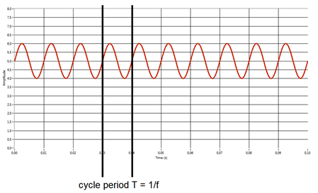
Figure 1: Display of the flicker frequency of a 100Hz oscillation with offset
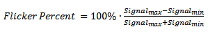
2.2 Flicker percent
The specification of the flicker percentage is widely used (e.g. IEEE 1789) and is also referred to as Modulation Depth. It indicates the magnitude (relative to the amplitude) of the waveform. The value ranges between 0% and 100%, with 0% signifying a pure DC waveform and 100% a pure AC waveform. This value has no implications on the duty cycle of the signal.
 (1)
(1)
Shown below is a graphical representation of the flicker percent computation:
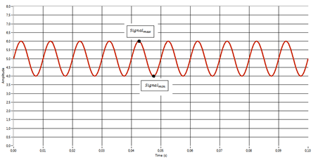
Figure 2: Display of the flicker percentage of a 100Hz oscillation with offset
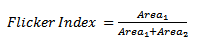
2.3 Flicker index
Besides the flicker percentage, the flicker index is also very significant. It indicates the ratio of the area under the curve to that over the curve. The center line corresponds to the average light intensity. Here, a value of 0 corresponds to a pure DC curve and 1 a pure AC curve. This factor specifies the duty cycle of the signal.
 (2)
(2)
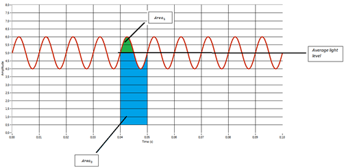
Figure 3: Display of the flicker index of a 100Hz oscillation with offset
2.4 SVM
Stroboscopic Visibility Measure, SVM, considers effects on appearance of moving and rotating objects when illuminated with light modulation typically up to 2 kHz. It is appropriate when the average light level is > 100 lx and the fastest movements are moderate speed hand movements of <= 4 m/s. If the SVM value equals to one, the input modulation produces a temporal light artefact that is just visible, i.e. just reaches the visibility threshold. In other words, an average observer will be able to detect the artefact with a probability of 50 %. If the value increases, the detection probability also increases. This visibility threshold represents the average detection ability of an average human observer in a population. A detailed described can be found in the open access document CIE TN006 [12] and IEC TR 63158.
2.5 PstLM
If the input modulation is not a periodic signal, the frequency-based method (FFT, etc.) cannot be easily used and a time domain based analysis is recommended. The short term flicker severity (Pst) from IEC 61000 [14, 15] became a widely accepted standard and is now proposed in CIE TN006 for the assessment of perceived light flicker for frequencies up to 80 Hz. In short the following steps are performed: normalization, temporal filtering and statistical processing.
The analyses of SVM and PstLM provides a good combination since the frequency based method of SVM and the temporal based PstLM allow the quantification of stroboscopic and light flicker respectively.
2.6 Assist Mp
The Assist Mp metric is a flicker perception metric which is designed to accurately predict human flicker perception for any lamp. It mainly deals with signals below 80Hz and which do not interact with moving objects or observers (stroboscopic or phantom array effect) [16].
The evaluation is based on 5 steps.
1: Acquisition of the light output signal
2: Application of Fourier Transform
3: Calculation of the Weber Temporal Contrast
4: Application of perceptual sensitivity weighting
5: Determination of combined frequency components
3. Flicker measurement using the BTS256-EF
3.1 Overview of the functions
The BTS256-EF is primarily a spectral but also integrating luxmeter. This is made possible by the BiTec sensor developed by Gigahertz-Optik.
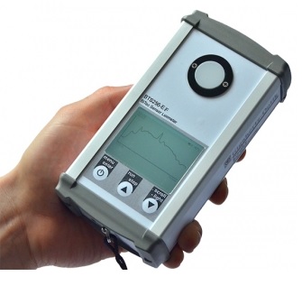
Figure 4: BTS256-EF, a spectral but also integrating luxmeter designed for mobile use.
One of the characteristic features of the device is its compact size, which makes it ideal for mobile use. The fact that it is splashproof also makes it well-suited for outdoor applications. A large memory is integrated, from which the S-BTS256 software can be read out. The device also has a user-friendly interface due to the numerous incorporated display options, some of which are customizable by the user. The well-matched cosine diffuser with a traceable calibration by national standards guarantees the precision of the measuring device, which can optionally be delivered with an integrated WiFi module.
In addition to photometric and scotopic measurements, the BiTec sensor enables flicker analysis as the diode used in the sensor makes it possible to perform evaluations in the same way as an oscilloscope. This means that the BTS256-EF performs parallel flicker parameter calculations of the light source to be measured during each measurement. These values are shown on a different screen layout:
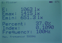 Figure 5: Display of the flicker parameters, E, Emax, Emin, flicker percentage, flicker index and flicker frequency
Besides calculation of the flicker parameters, the BTS256-EF also performs an internal FFT (Fast Fourier Transformation). This makes it possible to detect other frequency components in the signal. For instance, a 100Hz lamp can also contain frequency components in the 1 kHz range. At a workstation, multiple light sources can overlap which can result in superposition of different frequencies, whereby one of the signals may dominate the flicker with respect to the other frequencies. However, it may be important to investigate the flicker effects and their weighting due to these other frequency components. This evaluation can be performed on-site due to the FFT function integrated in the device. A maximum of six of the most dominant frequency components are displayed. It should be noted that high frequency signals with very low components can also exist in the FFT due to noise, therefore, a strong enough input signal is required:
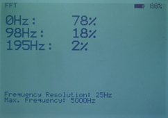 Figure 6: Example of a flicker measurement with three frequency components. The frequency is shown on the left column and the percentile component in the signal displayed on the right.
In addition to numerical display, a data logger view is also incorporated. This gives the user an optical overview of the signal. The high-resolution display of the BTS256-EF is in well suited for this, see Figure 7:
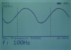
Figure 7: Graphical display of the light signal. The calculated period is shown between two perpendicular dotted lines.
Furthermore the BTS256-EF is able to analyze Assist Mp, SVM and Pst with the help of the S-BTS256 software. To make this data easily available to the user a specific display has been designed:
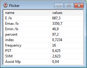
Figure 8: Display of the Flicker values in the S-BTS256 software
In addition the temporal signal can be analyzed in a data logger display.
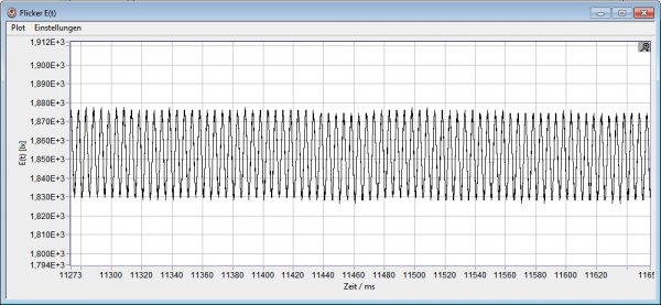
Figure 9: Display of the Flicker signal in the S-BTS256 software
3.2 Measurement accuracy and configuration
A few points should be noted when it comes to measurement accuracy. Basically, the signal to be measured should be strong enough (e.g. at least 100lx are recommended). Only then is it possible to guarantee a good signal to noise ratio for the flicker measurement. Figure 10 shows an example of a signal with a bad signal to noise ratio for the flicker measurement. The difference becomes obvious when figure 8 is compared with figure 7. This results in a decrease of the calculation accuracy of both the frequency and flicker parameters. How pronounced this effect is depends on the amplitude of the flicker signal, a large amplitude might be detectable even by the presence of noise. However, small flicker signals can be below the noise level and are thereby cannot be detectable. As a guideline the amplitude of the noise should be significantly smaller than the amplitude of the flicker signal.
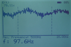
Figure 10: EA 78.11lx signal means a bad signal to noise ratio. The error in the calculation of the frequency and flicker parameters thereby increases greatly.
Furthermore, the diode measurement time (Menu Diode Settings → Measure Time) should be matched to the signal to be measured.
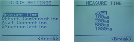
Figure 11: Setup of the measurement time from the BTS256-EF device menu.
This means that when the expected frequencies are very high, the shortest time constant of the diode (i.e. 50 ms) should be selected. The resulting maximum frequency is shown on the corresponding display (see Figure 7 with 5000 Hz). Very low frequency signals on the other hand require a much longer time constant (see Figure 11 with 1000 ms). The frequency resolution is hereby much better, but the maximum frequency to be determined consequently decreases.
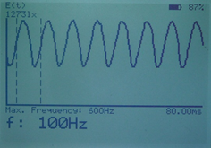
Figure 12: Display of a low frequency signal: Here, the maximum frequency to be determined for this signal strength is 600 Hz.
.
These measurement time configurations result in changes in the entire measurement time of the BTS256-EF. It is therefore recommendable to set the diode to the default 50 ms if the flicker function is not being used in order to shorten the entire measurement time of the device.
Overview of the various setups and the resulting parameters. Using as a handheld device without software, limited by internal storage:
| Measurement Time (Sensor) | Measurement Time (Flicker) | Sampling Rate | Upper Cut-Off Frequency | Lower Cut-Off Frequency | Frequency uncertainty at acceptable S/N ratio* | FFT frequency resolution |
| 50 ms | 41.0 ms | 20µs | 5kHz | 60Hz | 1%±0.5Hz | 25Hz |
| 100 ms | 81.9 ms | 40µs | 5kHz | 30Hz | 1%±0.5Hz | 12,5Hz |
| 200 ms | 163.8 ms | 80µs | 2.5kHz | 15Hz | 1%±0.5Hz | 6,3Hz |
| 500 ms | 327.7 ms | 160µs | 1.2kHz | 8Hz | 1%±0.5Hz | 3,2Hz |
| 1000 ms | 655.4 ms | 320µs | 0.6kHz | 4Hz | 1%±0.5Hz | 1,6Hz |
| 3000 ms | 2620 ms | 1280µs | 150Hz | 1Hz | 1%±0.1Hz | 0,4Hz |
| 6000 ms | 5240 ms | 2560µs | 75Hz | 0.5Hz | 1%±0.05Hz | 0,2Hz |
| 12000 ms | 10486 ms | 5120µs | 33Hz | 0.25Hz | 1%±0.02Hz | 0,1Hz |
By software controlled use the above analysis or the following high resolution analysis is possible:
| Measurement time (Flicker) | Sampling Rate | Upper Cut-Off Frequency (3dB) | Lower Cut-Off Frequency | Frequency uncertainty at acceptable S/N ratio* | FFT frequency resolution |
| min. 1 ms | 1 ms (1kHz) - 5 µs (200kHz) | 200 Hz - 10 kHz | 2,5 kHz | 1% ± 0,5 Hz | 1 kHz |
| max. 180 s (3 min) | 1 ms (1kHz) - 10 µs (100kHz) | 200 Hz - 10 kHz | 0,014 Hz | 1% ± 0,5 Hz | 0,005 Hz |
* by sufficient S/N
Important is also the signal level since not all amplifier ranges allow the fast response (3dB Range 0 to 5 = 10 kHz, Range 6 to 8 = 200Hz). For details see product page of BTS256-EF.
.
4. Flicker measurement using the PFL-200
The PFL-200 has the same amplifier as the BTS256-EF, but is equipped with a BNC (-1) detector in order to connect external detectors. The timing specifications are identical to the BTS256-EF.
5. Flicker measurement using the BTS2048-VL
In the BTS2048-VL the same signal amplifier design as in the BTS256-EF is implemented. Hence the same electro-optical performance can be achieved in terms of flicker. The BTS2048-VL is a high level remote operation BTS device which can be used for several applications where spectroradiometric measurements are needed, for instance as a sensor for illuminance measurements, detector for integrating spheres or as a detector for goniometric measurements (link datasheet).
Since the meter is a pure remote meter the flicker specifications are equal to the remote operation of the BTS256-EF and all parameters can be evaluated:
| Diode Measure Time | Sampling Rate | Upper Cut-Off Frequency | Lower Cut-Off Frequency | Frequency uncertainty at acceptable S/N ratio* | FFT frequency resolution |
| Can be chosen by the user. 180s (3 min) are needed for Pst evaluation, for others a shorter time is possible. | Can be chosen, min are 20µs (50kHz) | 5kHz | 60Hz | 1% ±0.5Hz | 25Hz |
* at sufficient S/N ratio
6. Summary
Several measurement parameters have proven to be important when it comes to evaluation of light sources with regards to flicker. These include the flicker frequency, flicker index and the flicker percentage, PstLM (CIE:TN-006, IEC 61000-4-15, IEC 61547 und IEC TR 61547-1), Assist MP (Assist Volume 3, Issue 3) and SVM (CIE TN-006). Several of these quantities can be directly measured using the BTS256-EF in handheld mode; all can be measured with the BTS2556-EF and BTS2048-VL in remote operation. The device enables analysis of different frequency components based on their weighting in the light signal using the integrated FFT (Fast Fourier Transform) analysis function. This is of particular interest when different frequencies or a dominant frequency together with high-frequency components are superimposed. The meters are designed for the detection of flicker frequencies up to 5 kHz. Parallel to the flicker parameters, the BTS technology also calculates all the relevant photometric data such as light intensity, color coordinates (x, y, u´, v´), color rendering index, TM-30-15, CIE2017, etc. In addition, the BTS256-EF stands out through its compact and splash-proof design, properties which make it excellent for mobile use where flicker examination should be carried out on-site e.g. for example at a workstation or in laboratory to check IEC 61000. The BTS2048-VL is becoming a standard in high quality and high speed LED testing such as binning, etc. Since it can be used as a detector for integrating spheres a very versatile measurement system can be achieved.
7. References
[1] Poplawski, M.E., Miller, N.M., Flicker in Solid-State Lighting: Measurement Techniques, and Proposed Reporting and Application Criteria, 1Pacific Northwest National Laboratory, Portland OR, USA
[2] Bullough, J.D., Sweater Hickcox, K., Klein, T.R., Lok, A., and Narendran, N., 2011. Detection and acceptability of stroboscopic effects from flicker, Lighting Research and Technology 0: 1-7.
[3] Bullough, J.D., Skinner, N.P., and Sweater Hickcox, K. 2012. Visual performance and perceived lighting quality under flickering illumination, Proceedings of the 13th International Symposium on the Science and Technology of Lighting, June 24-29, 2012, Troy NY, pp. 375-376.
[4] Fenton, D.M. and Penney, R. 1985. “The effects of fluorescent and incandescent lighting on the repetitive behaviours of autistic and intellectually handicapped children,” Journal of Intellectual & Developmental Disability, vol. 11, no. 3, p. 137–141.
[5] Fisher, R.S., Harding, G., Erba, G., Barkley, G.L., and Wilkins, A.J. 2005. “Photic-and Pattern-induced Seizures: Expert Consensus of the Epilepsy Foundation of America Working Group,” Epilepsia, vol. 46, no. 9, pp. 1426-1441.
[6] WILKINS, A.J., VEITCH, J.A., LEHMAN, B. 2010. LED lighting flicker and potential health concerns: IEEE Standard PAR1789 update. Proceedings of the Energy Conversion Congress and Exposition (ECCE) 2010 IEEE, 12-16 Sept., 2010, p. 171-178.
[7] IES RP-7: Recommended Practice for Lighting Industrial Facilities, 2001. Illuminating Engineering Society, New York, New York. Rea, M.S., The IESNA Lighting Handbook, 9th Edition, 2000. Illuminating Engineering Society, New York, New York.
[8] Veitch, J.A. and McColl, S.L., 1995. “Modulation of fluorescent light: Flicker rate and light source effects on visual performance and visual comfort,” Lighting Research and Technology: 27, no. 4, p.243.
[9] Vogels, I., Sekulovski, D., and Perz, M. (Est. 2011). Visible Artefacts of LEDs. Philips Lighting,Eindhoven, Netherlands.
[10] Wilkins, A.J., Nimmo-Smith, I.M., Slater, A. and Bedocs, L., 1989. Fluorescent lighting, headaches and eyestrain. Lighting Research and Technology 21: 11-18.
[11] Wilkins, A.J. and Roberts J.E., 2013. Flicker can be perceived during saccades at frequencies in excess of 1kHz. Lighting Research and Technology 45: 124-132.
[12] CIE TN-006, International Commission on Illumination
[13] IEEE Std 1789:2015 IEEE Recommended Practices for Modulating Current in High-Brightness LEDs for Mitigating Health Risks to Viewers
[14] IEC 61000-4-15, International Electrotechnical Commission
[15] IEC 61547 and IEC TR 61547-1, International Electrotechnical Commission
[16] Assist Mp, Assist Volume 11, Issue 3, January 2015, Lighting research Center