Overview of LED, Laser and VCSEL testing (SSL Testing) in production and other applications
Content
1. Brief description
This article will first describe the requirements of LED/SSL (LED = light emitting diode, SSL = solid state lighting) testing and the possible metrological solutions for different applications, ranging from applications in the production field and laboratory measurements, to on-site tests by users/customers. Gigahertz-Optik has over 30 years of experience in light measurement technology, and has taken a very innovative path in spectral measurement with the BTS technology.
2. Introduction
LEDs are increasingly being used for illumination purposes and as design elements. With many new applications and enormous market comes an increase in demands for LEDs and SSL in terms of the LED quality (i.e. spectral properties, such as color rendering, color fidelity, dominant wavelength, color location), energy efficiency (efficacy lm/W), and price. This means increased product quality with the increasing global competition, at falling prices. In terms of the quality, very precise, stable, and cost-friendly measurement techniques are required in addition to high-end and precise manufacturing methods, since LEDs cannot be produced with exactly the same optical properties due to the manufacturing processes involved. Optical properties can vary even within the same production batch. This thus necessitates comprehensive LED tests (intensity (W, lm, W/sr, cd) and color), as well as tests within the production process for various LED classes. In addition, the production cycle of LEDs is also decisive for their technical connection in applications. For instance, the heat sink has a decisive influence on the product stability and lifetime. Also SSL based Laser an VCSEL play an important role these days and measurement systems have to address this.
Figure 1 The LED technology is changing
3. Overview of SSL measurement requirements
3.1 Standards, norms, and guidelines for LED and SSL Testing
Certain specialist committees have developed guidelines in order to satisfy the metrological, electronic, and optical requirements. These offer a very good framework for users in terms of both the choice of a measurement technique, as well as key parameters. The following documents are hereby worth mentioning:
Released:
CIE84 | Measurement of Luminous Flux |
CIE127 | Measurement of LEDS |
CIE198 | Determination of Measurement Uncertainties in Photometry |
CIE214 | Effect of Instrumental Bandpass Function |
CIE S014 | Colorimetry |
CIE S025 | Test Method for LED Lamps, LED Luminaires and LED Modules |
LM-79-08 | Electrical and Photometric Measurements of Solid-Sate Lighting Products |
LM-80-08 | Measuring Lumen Maintenance of LED Light Sources |
DIN 5032-9 | Measurement of Photometric Quantities of Incoherently Radiating Semiconductor Light Sources |
CIE225 | Optical Measurement of High Power LEDs |
| CIE226 | High-Speed Testing Methods for LEDs |
| CIE233 | Calibration, Characterization and Use of Array Spectroradiometers |
Info: As a Silver Supportive Member of the CIE, Gigahertz-Optik GmbH supports the norm processing and helps ensure that metrological concepts are technically feasible. We also participate in DIN specialist committees. The process enables us to quickly respond to new requirements of our customers.
3.2 Difference in LED, VCSEL and Laser measurement requirements depending on the application
The measurement techniques must be adapted to the corresponding application. This means that industrial measurement in a production line has very different requirements from an on-site product quality check by the customer. The following basic requirements apply:
Applicable to all applications:
Very high demands in the stability of the measurement technique
Very high demands in the reproducibility and comparability of the measurement values
Low calibration uncertainty, traceability to national institutes and low measurement uncertainty
Excellent price-performance ratio, depending on the quality requirements
Testing in production lines
Fast and synchronized measurements
Compatibility (trigger options, etc.) with other measurement techniques e.g., Keithley 2400/2600 Source Meter or LPS20
Comprehensive software package with good support to facilitate integration in the customer’s system. Or complete measurement software.
Compact measurement system for integration in wafer probes/test machines (in front- and back-end binning)
Laboratory applications/incoming goods inspection/Production-assistant QA
Very flexible, possibly modular measurement concept to facilitate different measurement tasks
Measurement under controlled conditions e.g., junction temperature
Compatibility (trigger options, etc.) with other measurement techniques e.g., Keithley 2400/2600 Source Meter or LPS20 LED drivers
On-site application tests by the customer/user
Hand-held measurement device/mobile device
Suitable for outdoor use (temperature correction, splash-proof, very robust, compact)
Easy and intuitive operation without warm-up time
Favorable price/performance ratio, adapted to the requirements of the different applications.
3.3 Key Parameters of LED and VCSEL Measurement Equipment
Specialist committees (e.g., CIE and IES) have specified different standards, norms, and guidelines for essential device parameters based on scientific publications. Below are some of the parameters:
LED and SSL Light Meter (Spectroradiometer):
Spectroradiometers are largely used in LED/SSL measurement technology.
Calibration Uncertainty:
Calibration of spectroradiometers must be traceable to national standards e.g., PTB or NIST. Calibration must also be performed in a qualified and experienced calibration laboratory, since the calibration quality is decisive for the usability, reproducibility, and comparability of measurement devices.
Note: Gigahertz-Optik has its own, accredited (DAkkS: D-K-15047-01-00) calibration laboratory for spectral irradiance and spectral responsivity, to ensure the best possible calibration quality and quality assurance of its products.
Measurement Uncertainty:
Besides the calibration uncertainty, measurement uncertainty is also critical, since the light source to be measured is often different from that used in the device calibration. Different factors (environmental conditions) at the measurement location must also be considered (see CIE198 and CIE S025). For this reason, an additional measurement uncertainty test must be performed. For the user, this means that a comprehensive characterization of the spectroradiometer is necessary, and these parameters must be available from the manufacturer.
Reproducibility:
Both the reproducibility of the measurement results and reproducibility of the mechanical adaptation, e.g. to the integrating sphere or luminous intensity adapter, are necessary. Mechanically, these adapters must be well thought out and sturdily constructed. Here, optical fibers are more vulnerable, and are therefore a bit more demanding compared to more stable, closed systems.
Optical Bandwidth:
Less than 5 nm or bandwidth-corrected (e.g., 10 nm with bandwidth correction) in accordance with CIE214. Suitable for laboratory and application measurements. Optical bandwidths of less than 3 nm can be an ideal choice for industrial applications, e.g. LED binning, to raise the accuracy in color measurement. The optical bandwidth distorts the spectrum, for example when lines or peaks are spread from LEDs (see "Basics of Light Measurement").Wavelength Accuracy:
For application measurements, this should be better than ± 0.5 nm to allow for sufficient precision in color coordinate measurements. For high-precision binning applications, the wavelength accuracy should be better than ± 0.2 nm. This accuracy is extremely essential in color coordinate measurements, and therefore also plays one of the largest roles in the measurement uncertainty. In addition to precision, the stability of the wavelength calibration is also key to stable results.
Stray Light Suppression:
Stray light suppression (see note below) is particularly relevant for measurement of white LEDs. Insufficient suppression of stray light can for instance cause the color location to shift. Stray light suppression of no less than 10E-3 is required for sufficiently accurate measurements. High-end spectroradiometers (e.g., optical beam paths with ZEMAX simulations, etc.) can comfortably meet this requirement thanks to their hardware properties. Stray light matrix calculation, as per (Zong et al., 2006) or (Nevas et al., 2012), principally allows for an even better suppression of the stray light. Besides the wavelength accuracy, sufficient stray light suppression is crucial for precise color location measurements.
Note: Stray light suppression is the avoidance of stray light/false light with wavelengths different from the one being used. For instance, the signal from a white LED in a spectrometer can produce stray light that is detected by detector pixels in the spectral range below 400 nm. This signal is then reproduced in the measurement data, even though physically, it does not directly result from the LED but rather due to a measurement error of the spectroradiometer. This measurement error can lead to shifting of the color location. The main problem with stray light is that it is highly dependent on the measured light source and its spectral distribution. Thus, the best possible stray light suppression should always be strived for, in order to avoid or reduce this uncertainty.
Trigger Options:
Particularly in industrial applications, with time-clocked production processes, the measurement device is often not the controlling device. Trigger options should therefore be integrated, e.g. to allow the current source (e.g. a Keithley 2400/2600 or LPS20) to trigger the measurements. Here, precise synchronization requires the least possible jitter between the trigger input port (i.e. current supply to the measurement object) and measurement start (start of the measurement with the spectroradiometer).
Linearity:
The linearity of CCD and CMOS detectors is not enough to meet the demand of precise spectroradiometric measurements at all drive levels and integration times. High-quality measurement devices are therefore fitted with completely linearized detectors.
Note: The BTS technology from Gigahertz-Optik allows for integration of an additional detector as a reference or correction factor, and thus guarantees high linearity over a large dynamic range.
Dynamic Range:
For a wide dynamic range, the ADC should have the appropriate resolution for the specific application (e.g. 16 bit in LED binning). In addition, it should allow for an adjustable integration time. This measurement range can also be enhanced using an OD filter. Dynamic control mostly by the integration time helps avoid the time-intensive replacement of the OD filter during use, and thus helps avoid further calibration uncertainty through the OD filter (spectral path, aging). The effect of the OD filter on the measurement uncertainty must be considered, e.g. through own calibration entries of the OD filter.
Note: The BTS2048-VL covers an integration range of 2 µs to 60 s. These are over 7 orders of magnitude in terms of the dynamics simply via the integration time.
Long-Term Stability:
Aging of a measurement system must be taken into account in the measurement uncertainty and should be very low for high-quality measurement systems. This also helps keep the recalibration cycles as long as possible. The long-term stability is particularly important in terms of the wavelength accuracy. Failure to ensure this could result in large shifts in color measurements (color location, dominant wavelength, etc.).
Note: In luminous flux measurements, the integrating sphere is part of the input optics, and hence also a part of the measurement system. Its aging must therefore be considered as well. The BTS technology is a two-sensor technology, which has an added advantage since the extra reference sensor also automatically detects possible shifts.
Temperature Correction:
Temperature correction is important to ensure correct absolute measurement values (e.g. irradiance), as well as compensate for wavelength errors, especially in outdoor measurements
Note: Here as well, the BTS technology is highly advantageous compared to conventional spectroradiometers, since it allows for an online temperature correction of the measurement data.
Input Optics for different LED Testing Measurements
Luminous flux measurement:
Integrating spheres → Different applications require different sphere geometries. 2pi measurement geometries are often preferred in production lines, since they allow for fast and easy placement of the measurement object in the sphere. Combined 2pi or 4pi integrating spheres are a good choice for laboratory applications since they offer a high flexibility level in terms of position of the measurement object. In addition, rotatable spheres are a good option for measurement of the lamp in its application position.
Note: Gigahertz-Optik GmbH has decades of experience in manufacturing of integrating spheres, and offers the necessary expertise and versatile design options in the selection and configuration of the spheres.
Luminous intensity measurement:
ILED-B or ILED-A adapters → The LED average intensity adapter (A or B) has established itself in LED measurement technology through its fast and reproducible results. Both variants require a 1 cm² homogeneous responsivity area and a defined measurement distance (ILED-B = 100 mm → 0.01 sr, ILED-A = 316 mm → 0.001 sr). ILED-B is more widespread due to its additional advantages associated with its shorter measurement distance and the resulting shorter measurement times (factor of 10).
Wafer Tester/Wafer Prober:
Some production lines require inspection/sorting during manufacturing on the wafer. This uses the so-called wafer testers. These are special, high-sensitivity, fiber-based input optics that allow for the shortest possible measurement times and precise positioning directly on the wafer in front of the desired LED. They are mostly calibrated in irradiance and radiance. In principle, they are a modification of the ILED-B or ILED-A measurement geometry for a different requirement.
Illuminance:
COS diffuser → COS diffusers that are perfectly adapted across the entire spectral range of the spectroradiometer are very important for precise illuminance measurements. If they are not integrated, spectral measurement errors can result for large incident angles, due to a different COS weighting of the measurement signal.
LED and SSL Testing Electrical measurements
Source & measurement:
Current sources should comply with the CIE S025 guidelines. This means that the calibration uncertainty of the current source, its bandwidth, etc. must be considered. A ± 0.4 % RMS for DC voltage sources and ± 0.2 % for DC current source must be adhered to. Voltage measurement for DC should be better than 0.1 %. In pulsed operation mode, it should be possible to synchronize the power supply with the measurement device through trigger options.
Note: Gigahertz-Optik uses current sources and measurement devices by Keithley or from its own production.
Software Needs for LED and SSL Testing
In order to avoid operational errors and additional costs, intuitive software and good support are required for integration of the measurement technology in application processes, and to ensure correct measurements. The software must also support customization to meet the specific requirements of users. It should allow for inspection and monitoring of different devices, as well as support logical operations and evaluations. In addition, it should be able to provide fast, reliable, and precise calculation parameters. Fast and easy integration of new parameters, e.g. the IES TM-25 or IES TM30-15, must also be taken into account.
Environmental Conditions for LED and SSL Testing
CIE S025 specifies guidelines for laboratory and framework conditions. These include the ambient temperature (tolerance interval ± 1.2 °C), surface temperature, draft, etc. It also specifies guidelines for the accuracy of the electric measurements.
4. Measurement Solutions and Possibilities in LED, VCSEL and SSL Testing
The different norms, e.g. those mentioned under 3.1, serve as a guide for the measurement implementation. However, a good solution is not just about meeting these stipulated norms, but also keeping the solution practical, cost-friendly, and fulfilling the requirements of users. At Gigahertz Optik GmbH, we place great value in this and have over 30 years of experience in the production of measurement systems that meet the requirements of customers, their respective applications, and the applicable norms. Below are some examples:
SSL Testing in Production Lines
The BTS2048-VL series is characterized by its optical properties, extensive electronics, compact design, and flexibility in these applications. In terms of its optical properties and quality, the device is in the upper class of spectroradiometers (see BTS2048 Series from 200 nm to 2150 nm). It can be connected directly to an integrating sphere for measurement of the luminous flux and different color measurements. The connection to an ILED-B adapter allows for irradiance measurements as per CIE127. Both measurement geometries are commonly used by established LED manufacturers for LED binning.
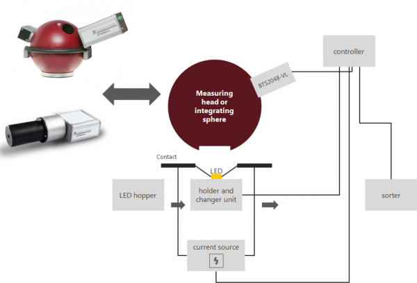
Figure 2 BTS2048-VL with ISD-xxx (top-right) in schematically illustrated in a production line (top-left). The BTS2048-VL with an ILED-B adapter (bottom)
Thanks to the integrated electronic shutter, the BTS2048-Series enables significantly shorter integration times (shorter than 2 µs) compared to other devices in this class (µs range). This increases the dynamics 1000 times without OD filters. Use of OD filters increases the dynamics even further. The modern and powerful electronics, which include a variety of interfaces (ethernet, USB, …), make it possible to perform fast measurement sequences, i.e. the waiting time between measurements is reduced. For instance you can have a 1 ms measurement with a delay of just 6 ms. This saves time in production and thus also costs (more information can be found here.
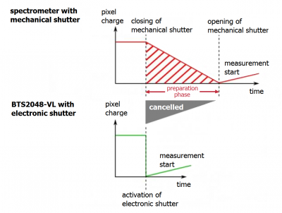
Figure 3 The electronic shutter of the BTS2048-VL shortens the waiting time between two subsequent measurements. The powerful electronics enable much faster calculations and data transfer.
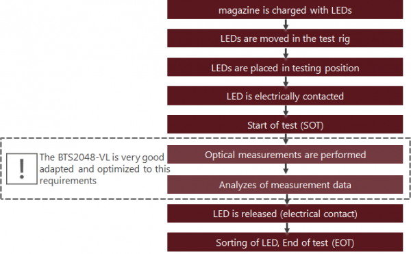
Figure 4: Basic sequence of a binning process in production
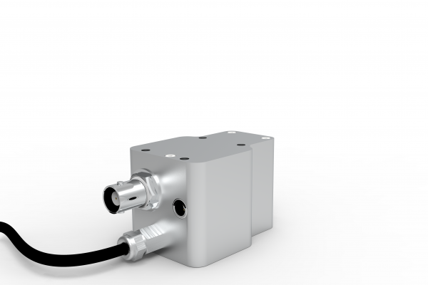
Also the integral super fast measurement of pulse shapes, pulse intensity of lasers is important when talking about for instnace LiDAR applications. The ISD-1.6-SP-Vxx is a measurement system to address these needs with a fast (ns) diode for pulse shapes and a precise (µs to ms) diode for pulse energy.
Laboratory Applications / Quality Control /Production Assistant QA
The BTS256-LED Tester series is a versatile technology for laboratory applications. Being a handheld device, the BTS256-LED is well suited for measurement of individual LEDs. A quick-mount diffuser lens and the device’s bayonet connector enable the device to be connected to a goniometer, or used as an irradiance meter for spot lamps. The bayonet connector also makes it possible to connect the device onto different integrating spheres. It is the ideal spectroradiometer for versatile measurement tasks in a laboratory. (More information can be found here).
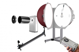
The same concept can also be used with the BTS2048 Series series for even higher quality measurements (more information can be found here.
The TPI21-TH is a plug & play test system for single LEDs (Star, SMD, etc.) or LED assemblies with diameters of up to 70 mm. All functions necessary for measurement of LEDs using the Keithley Source meter, the high-quality spectroradiometer (BTS2048-VL), and measurement with thermoelectric cooling and heating (LEDA-7-TEC) are run by the system software. Specifications for the measurement cycle can be set individually be the user. The S-BTS2048 software also supports a complete measurement data analysis. Generally, its properties allow this system to perform measurements in accordance with DINv5032-9 and CIE S025. The optional light-tight measurement chamber enables the measurement system to be used in illuminated production locations.
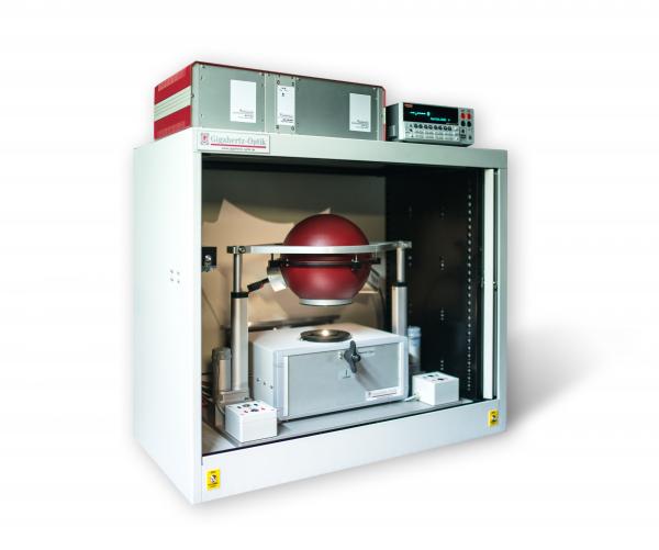
Figure 5 TPI21-TH measurement system in the optional measurement chamber
On-site Application Test by Customer or User
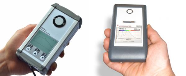
We have two devices designed for measurement of the illuminance, irradiance, luminous color, and the CRI. These are developed for different technical requirements to provide customers with the ideal measurement device for their application. The BTS256-EF series is a high-quality, BTS-based handheld meter with good stray light suppression, wavelength accuracy, etc., for the highest possible precision in field applications. With this device for instance precise color coordinate measurements can be performed (Mac Adam ellipses, Binning fields, etc.) for quality control purposes or inspection. Furthermore the EF version is able to measure flicker parameters directly on site.
The MSC15 and CSS-45 is more like the little brother to the BTS256. It is priced significantly lower with slight compromises in terms of optical and functional performance. This is compensated for by the ease of use and intuitive software.
5. Summary
The requirements in LED/Laser/VCSEL (SSL) testing are changing rapidly due to the rapid development in LED technology. In terms of the measurement technology, the main challenge lies in fulfilling the stipulated norms and standards, and at the same time meeting the requirements of users. In addition, short development times and good customer support are necessary for measurement techniques to also match up to the speed of LED development. With over 30 years of experience, Gigahertz Optik GmbH is an expert in the development of this measurement technology, and with its modular product portfolio and high-quality calibration laboratory, it is the ideal partner for all current and future requirements.
6. Literature
Nevas S, Wübbeler G, Sperling A, Elster C and Teuber A 2012 Simultaneous correction of bandpass and stray-light effects in array spectroradiometer data Metrologia 49 S43
Zong Y, Brown S W, Johnson B C, Lykke K R and Ohno Y 2006 Simple spectral stray light correction method for array spectroradiometers Appl. Opt. 45 1111-9
CIE84, Measurement of Luminous Flux
CIE127, Measurement of LEDS
CIE198, Determination of Measurement Uncertainties in Photometry
CIE214, Effect of Instrumental Bandpass Function
CIE S014, Colorimetry
CIE S025, Test Method for LED Lamps, LED Luminaires and LED Modules
IES LM-79-08, Electrical and Photometric Measurements of Solid-Sate Lighting Products
IES LM-80-08, Measuring Lumen Maintenance of LED Light Sources
DIN 5032-9 Messung der lichttechnischen Größen von inkohärent strahlenden Halbleiterlichtquellen