Optometers, Amplifiers, Display Meters
Optometers are a specific type of digital multimeter (DMM) used for optical radiation measurements. The particular light detector(s) connected determine the wavelength range/spectral weighting function and displayed measurement units.
We offer a modular range of broadband light detectors which can be combined with our wide selection of optometers and amplifiers. In addition to its standard products, Gigahertz-Optik also offers customized solutions.
Step 1: As a first step we recommend the selection of a detector head. It is also possible to use several detector heads, which can be used interchangeably with single-channel meters or simultaneously with multi-channel meters. The selection criteria for a detector head include the required measurement quantity and range, its spectral function, and all other parameters relevant to the intended use.
Step 2: In the second step, accessories such as e.g. an integrating sphere can be selected. If the accessory changes the detector head’s measurand geometry and responsivity, an additional calibration for the detector head with accessories in the corresponding measurand must be selected.
Step 3: In the third step, the meter is selected. The planned use (e.g. mobile, stationary, manual or remote-controlled), the number of signal channels, the measurement mode (CW, dose, pulse energy, temporal pulse progression) are all decision criteria.
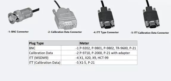
Step 4: The connection of the measuring device for the detector head determines the connector type of the detector head. Gigahertz-Optik’s detectors are designed with connectors of the following four types:
- Connector Type -1: Conventional BNC coaxial connector
- Connector Type -2: Calibration Data Connector with Eeprom for storing the detectors data (type, calibrated responsivity) read by the connected meter.
- Connector Type -4: Compact plug for detector heads with up to four photodiodes.
- Connector Type -5: Compact plug with calibration Eeprom

Step 5: To determine the measuring range of a selected configuration, two specifications of the selected detector head and meter are required. The typical sensitivity (e.g. A/lx) and the max. permissible signal current of the detector head. The minimum and maximum input signal of the measuring range of the meter.
Detection Limit (Noise Equivalent Power, N.E.P.) = Minimum input signal of the meter (A) / typical detector sensitivity (e.g., 0.1 pA / 3 nA / (mW / cm²) = 0.33 nW / cm². (*1) (*2)
Maximum reading = maximum input signal from the meter (A) / typical detector sensitivity (e.g., 20 μA / 3 nA / (mW / cm²) = 6.66 W / cm². (*3)
Remarks:
(*1) The minimum measurable value of the broadband light meter or radiometer results from the desired signal-to-noise ratio (SNR). For a DIN Class A lux meter, e.g. a minimum SNR of 100 is given. For the detector head of the example calculation, an SNR of 100 would mean a minimum measureable value of 33 nW / cm². For applications in the limit area of optical radiation measurement technology, it is common to use lower SNR of 50 or even 10.
(*2) In the case of very low detector current signals, movements of the cable between the detector head and the meter can lead to short, capacitive interference signals. In addition, strain effects on the plug of the detector head may increase the noise signal.
(*3) The maximum calculated measurement value reflects the large dynamic range of semiconductor photodiodes. In practical application, however, the maximum measurable value is often limited by the temperature radiation contained in the measured optical radiation, which would mean unacceptable heating of the detector head.
Optometer respectively Current Amplifiers for Radiometric or Photometric Applications
| Model | Photo | Detector Inputs | N.E.I. Noise equivalent input / integration time | Max. signal input | Gain ranges | Integration time range | Remarks | |
|---|---|---|---|---|---|---|---|---|
| X1 |

|
1 / 4 channels multiplexed | 0.1 pA / 500 ms | 200 µA | 7 |
1 ms – 1 s |
Best selling optometer for general applications. X1-Z03 option to connect up to four detectors (with BNC connectors). | |
| P-21 |

|
1 | 0.1 pA / 100ms 0.005 pA / 5 s (*1) | 2 mA | 8 |
100 μs – 5.9999 s |
Highest quality portable optometer with color touchscreen, analog output and trigger. Very large dynamic range. Lowest input offset for smallest measurement signals. Many measuring functions. | |
| PFL-200 |

|
1 / BNC | 0.1 pA / 5 µs sampling time min at min. measurement time 100 µs | 20 µA | 9 | Fast amplifier for flicker measurements of Pst, SVM and other metrics or measurements which need fast sampling (up to 200 kHz). | ||
| P-9710-1 |

|
1 | 0.1 pA / 100ms 0.005 pA / 5 s (*1) | 2 mA | 8 |
100 μs – 5.9999 s |
High quality portable optometer. Very large dynamic range. Lowest input offset for smallest measurement signals. Many measuring functions. | |
| P-9710-2 |

|
1 | 0.1 pA / 100ms 0.005 pA / 5 s (*1) | 2 mA | 8 |
100 μs – 5.9999 s |
Identical to the P-9710-1 but with 20 ms time constant in all amplifier gain ranges for measuring the pulse energy according to the streched-pulse method. | |
| P-9710-4 |

|
1 | 0.1 pA / 100ms 0.005 pA / 5 s (*1) | 2 mA | 8 |
100 μs – 5.9999 s |
Identical to the P-9710-2 but with additional trigger input for synchronizing the measurement of pulse energy. | |
| P-9801 |

|
8 | 0.1 pA / 100 ms | 2 mA | 8 |
1 ms – 999.999 s |
High-quality 8-channel optometer with 8 separate signal amplifiers. P-9801-V02 has 20 ms time constant in all amplifier gain ranges for measuring the pulse energy . P-9801-V03 has short time constants in all amplifier gain ranges for data logger applications. | |
| P-9802 |

|
up to 2 x 18 / multiplexed | 0.1 pA / 100 µs | 200 µA | 7 |
20 ms to 4 s (set by RS232 command) |
Individually configurable optometer with up to 36 separate signal inputs. | |
| P-2000-1 |

|
2 / multiplexed | 0.1 pA / 100ms 0.005 pA / 5 s (*1) | 2 mA | 8 |
100 µs – 5.9999 s |
High quality 2-channel optometer. Very large dynamic range. Lowest input offset for the smallest measurement signals. P-2000-2 has 20 ms time constant in all amplifier gain ranges to measure the pulse energy. | |
| TR-9600-1 |

|
1 | 60 pA / 1 µs | 2 mA | 10 | Fast data logger optometer with 1 μs time constant. Transient recorder with 12-bit ADC adjustable from 10 M samples/s to 1 k sample/s sampling rate. 4M bytes of memory. | ||
| TR-9600-2 |

|
1 | 20 nA / 100 ns | 600 µA | 4 | Fast data logger optometer with 100 ns time constant. Transient recorder with 12-bit ADC adjustable from 10 M samples / s - 1 k sample / s sampling rate. 4 M bytes of memory. | ||
| X1-RM |

|
1 / 4 chanel multiplexed | 0.1 pA / 500 ms | 200 µA | 7 |
1 ms – 1 s |
Optometer module for installation in 19" systems. I / O, USB and RS485 interfaces. |
Note: (*1) Offset measurement before each measurement recommended
Signal Amplifier and Current Amplifier
| Model | Image | Detector Inputs | N.E.I. Noise equivalent input / integration time | Max signal input | Gain ranges | Slew rate (10% to 90%) | Remarks | |
|---|---|---|---|---|---|---|---|---|
| PLL-1701 |

|
SMA / 1 | 9 lin & 1 log | 16 µs or 500 µs | Fibre and current input, Lin. or Log current amplifier | |||
| PFL-200 |

|
1 / BNC | 0.1 pA / 5 µs sampling time min at min. measurement time 100 µs |
20 µA |
9 | 3dB cut-off: Range 0 to 5 = 10 kHz, Range 6 to 8 = 200Hz | Fast amplifier for flicker measurements of Pst, SVM and other metrics or measurements which need fast sampling (up to 200 kHz). | |
| P-9202-4 |

|
1 | 10 mV pk-pk |
± 5 mA |
8 | 1 µs - 3 µs | Transimpedance amplifier - fast | |
| P-9202-5 |

|
1 | 4 mV pk-pk |
± 5 mA |
8 | 5 µs - 20 ms | Transimpedance amplifier - general purpose | |
| P-9202-6 |

|
1 | 0.5 mV eff |
± 1 mA |
8 | 25 ms - 2.5 s | Transimpedance amplifier - very high sensitivity |