Luminous Flux and Color Measurement of Board Mounted LEDs
Manufacturers offer LEDs sorted or ‘binned’ according to their Correlated Color Temperatures (CCT), lumen output, and forward voltage parameters. For example, standards such as ANSI C78.377-2017 [1] specify the range of chromaticity values recommended for general lighting in terms of ‘bins’ that are defined by a series of chromaticity quadrangles plotted along the black body locus in the CIE 1931 or CIE 1976 color space.
Need for Quality Control in LED Production
Although this pre-sorting limits tolerance ranges, it does not release the user from metrological quality control. This is mainly due to the fact that the operating parameters used for LED binning do not match those of the end application.
Manufacturers classically specify bins for their devices based on measurements using ~20 ms current pulse operation and with a junction temperature of 25°C. These days methods as described in LM-92-22 "Optical and Electrical Measurement of Ultraviolet LEDs" [2] like
- Continuous Pulse Measurement Techniqe for LED measurement
- Differential Continuous Pulse Method for LED measurement
- Mean Differential Continuous Pulse (M-DCP) Method for LED measurement
- DC Method for LED measurement
- Continuous Pulse Time Resolved (CPT) Method for LED measurement
are known and widely used. Therefore, in addition to the particular current drive conditions employed, the thermal design of the LED carrier board and associated heatsink can significantly influence the optical performance of any assembled LED module or product. Also timing issues and jitter considerations are important and are all part of the measurement uncertainty evaluation.
Measurement Systems for on Board LED Testing
The two possible measures of the light intensity of assembled LEDs are luminous flux (lm) and luminous intensity (cd). The measurement of the luminous flux is preferable to the measurement of the luminous intensity, since no particular alignment of the measuring device with the beam of the LED is necessary. The BTS256-LED tester incorporates an integrating sphere in conjunction with its BiTecSensor technology enabling the direct measurement of the luminous flux, spectral power distribution, CCT and color rendering (CIE CRI and IES TM-30-15) of in-situ LEDs. The cone-shaped measuring aperture of the integrating sphere is simply positioned over the assembled LED for measurement.
The measurement of UV LEDs, VIS LEDs and NIR LEDs on board for quality control can be perfectly done with our measurement equipment. This of course ISO 17025 traceable calibrated.
References
[1] Specifications for the Chromaticity of Solid State Lighting Products, ANSI C78.377-2017
[2] LM-92-22: Optical and Electrical Measurement of Ultraviolet LEDs
Quality Control of LED Spotlight Manufacturing Processes with a Single Measuring Device
The development and manufacture of good quality LED spotlights requires an extensive range of photometric and colorimetric measurements. The investment required for equipping and operating a comprehensive photometric test laboratory can seem prohibitive for the many medium-sized manufacturers offering products in this marketplace. Therefore, the possibility of a universally applicable and compact measuring device for the various measurement tasks is attractive.
The optical parameters that are required to be measured in the development and production processes of LED spotlights include:
- Luminous flux and chromaticity including CCT of the LED
- Luminous flux and chromaticity including CCT of the LEDs assembled on PCBs
- Luminous flux and chromaticity including CCT of the LED with optics
- Luminous intensity
- Luminous intensity spatial distribution
These photometric and colorimetric measures require a selection of input optics configured with a suitably calibrated spectroradiometer. With the BTS256-LED Plus Concept Gigahertz-Optik GmbH offers an affordable spectroradiometer with accessories for all of the above listed measurement tasks.
Measurement of Solid-State Lighting for Indoor Work Places
Constantly changing measurement environments
LED technologies, collectively referred to as solid-state-lighting (SSL), have revolutionised the field of general lighting creating exciting possibilities, but also bringing measurement challenges for manufacturers and installers alike. The development and manufacture of LED devices, LED lamps, and LED luminaires all require extensive testing and qualification. For this purpose, high-quality light measurement systems for spectral characterization are used, which provide precise measurement data. However, the planning and verification of SSL schemes also benefit from spectral and color measurement capabilities not offered by the lux meter products traditionally used for such purposes.
The European standard, EN 12464-1 [1], defines lighting requirements for indoor work areas.
The standard includes the following measurement criteria based on the intended use of the lighting:
- the minimum required average illuminance per task (referred to as “maintained illuminance”);
- the minimum required color rendering (specified as a minimum CIE Ra value).
Accurate Indoor Work Place Measurement System
The spectral distribution of SSL can be very different to that of traditional lighting technologies resulting in potentially significant errors in illuminance measurements made with filter-based lux meters. Determining the color rendering index requires the measurement of the spectral power distribution of the light. Therefore, both measurement requirements are best satisfied by light meters with full spectral measurement capability such as the MSC15 versatile spectral lux meter which eliminate the spectral mismatch errors of lux meters and yield full colorimetric data. The BTS256-EF spectral light meter optimized as mobile transportalbe meter, for example, also permits the assessment of light flicker and stroboscopic effects.
References
[1] EN 12464-1:2011 Light and lighting. Lighting of work places. Indoor work places.
Measurement of LED Grow Lights used in Horticulture
Opportunities of the LED/SSL Technology
LED lighting offers horticulturalists many potential benefits such as increased crop yields, improved product quality, and control of particular plant characteristics as well as the normal solid-state lighting benefits of reduced energy and maintenance costs. LED lighting can supplement natural sunlight within greenhouses to extend fruit, vegetable and flower growing seasons, particularly during the shorter days of winter.
LEDs allow control of the amount and spectral composition of light which can be used to govern a plant’s growth rate, shape and flowering. LEDs can also be positioned much closer to foliage than traditional lighting technologies, such as high pressure sodium lamps, as they do not radiate heat.
Therefore, energy efficient LED grow lights are a key enabling technology for a new form of horticulture, known as vertical farms, where crops are grown in vertically stacked layers in the absence of any natural daylight typically. Vertical farms are expected to play an important role in feeding the rapidly growing population of our increasingly urbanized world.
Requirements for precise PAR Meters
The horticultural world is very active researching spectral and intensity mixes, often referred to as "lighting recipes", to optimise crop growth and yield with LED lighting. Development and use of these "lighting recipes" in modern horticulture requires spectral measurement data on the pure and mixed colours produced by LED grow lights. This requires a new generation of sensor to replace the traditional PAR sensor, a quantum device that provides no spectral information. The MSC15 is a convenient, low-cost spectral light meter, ideal for routine measurements of LED lighting within horticulture. The additional functions of the BTS256-EF lend itself to more demanding horticultural research tasks.
In 1972, K. McCree [1] demonstrated that photosynthetic response correlates with the amount of photons that reach a plant rather than the energy of the light. See Technical Article – Measurement of PAR for an in-depth explanation. Photosynthetically Active Radiation, PAR, is just a descriptive term for radiation within the 400-700nm wavelength range (CIE Publication 106) [2]. The commonly used quantitative PAR terms are:
- Photosynthetic Photon Flux (PPF): measurement of the total number of photons emitted by a light source each second within PAR wavelength range. Measured in μmol/s. Analogous to ‘lumens’ for visible light.
- Photosynthetic Photon Flux Density (PPFD): measurement of the total number of photons within PAR wavelength range that reach a surface each second measured over a one square meter area. Measured in μmol/m2/s. Analogous to ‘lux’ for visible light.
- Day Light Integral (DLI): cumulative measurement of the total number of photons within PAR wavelength range that reach a surface during 24 hour period, measured over a one square meter area. Measured in mol/m2/d.
Besides optimising photosynthetic response, LED lighting offers many possibilities to exploit the fact that plants have additional photoreceptors responsive to UV and far-red radiation that impact plant development. This has prompted the American Society of Agricultural and Biological Engineers, ANSI/ASABE S640 [3], to introduce new metrics such as:
- Ultraviolet Photon Flux Density (PFDuv), 280 nm to 400 nm
- Far-Red Photon Flux Density (PFDfr), 700 nm to 800 nm
References
[1] Ref 1 McCree, K.J., 1972. The action spectrum, absorptance and quantum yield of photosynthesis in crop plants. Agric. Meteorol. 9: 191-216.
[2] Definition PAR metric (CIE Publication 106, Section 8, 1993
[3] ANSI/ASABE S640 JUL2017 Quantities and Units of Electromagnetic Radiation for Plants
Light Measurement Requirements for Human Centric Lighting
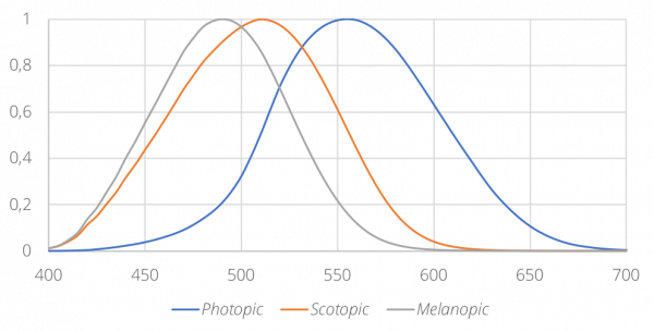
Contemporary scientific research has shown that in addition to the cones and rods that provide us with color and night-time vision respectively, our retinas also have non-image forming photoreceptors, called intrinsically photosensitive retinal ganglion cells (ipRGCs), which play a major role in entraining our circadian rhythms. Of particular interest is the spectral responsivity of ipRGCs which contain a photopigment called melanopsin. Whereas our cones and rods have spectral responsivities defined by the V(λ) and V’(λ) functions for photopic and scotopic vision, ipRGCs have their own ‘melanopic’ spectral responsivity with peak sensitivity in the blue spectral region, around 480nm.
SSL Possibilities for HCL
Modern insights into human chronobiology combined with the possibilities of SSL lighting offer many new opportunities to improve health and wellbeing through appropriate lighting, most commonly referred to as ‘human centric lighting’ (HCL), but other terms such ‘circadian lighting’, ‘biodynamic lighting’ or ‘biologically-effective lighting’ are also regularly used.
In its basic form, HCL typically attempts to control the Correlated Color Temperature (CCT) of lighting in a way that emulates natural daylight. More sophisticated techniques involve the measurement of additional metrics such as melanopic illuminance (CIE TN 003:2015) [1] or Circadian Stimulus (LRC Rensselaer) [2]. The accurate measurement of all of these metrics requires spectral characterization of the lighting.
The measurement of ‘equivalent melanopic lux’ (EML or melanopic illuminance), as required by the WELL Building Standard [3] for example, and ‘melanopic daylight equivalent illuminance’ are standard features of all our spectral light meters, including the low cost MSC15-CS meter which is approved by the International WELL Building Institute for such measurements.


Works with WELL TM licensed by International WELL Building Institute
HCL Measurement Systems
HCL is not only concerned with our ipRGC response to the amount and timing of ‘blue light’ received. Rod and cone photoreceptors also contribute to our circadian phototransduction. Knowledge of other wavelengths may also prove useful to HCL designers. For example, ‘red light’ has been shown to increase alertness without suppressing melatonin. For research purposes, the CIE now recommends (CIE TN 003:2015) [1] reporting all of the 5 α-opic equivalent illuminances for s-cones, m-cones, l-cones, rods and ipRGCs. Accordingly, the BTS256-EF spectral light meter and the BTS2048-VL laboratory spectroradiometer report the following metrics:
| α-optic |
| unit |
| Ez | melanopic illuminance | z-lx |
| Ee,z | melanopic irradiance | W/m² |
| Ev,mel | melanopic daylight equivalent illuminance | lx |
| Esc | cyanopic illuminance | sc-lx |
| Ee,sc | cyanopic irradiance | W/m² |
| Emc | chloropic illuminance | mc-lx |
| Ee,mc | chloropic irradiance | W/m² |
| Elc | erythropic illuminance | lc-lx |
| Ee,lc | erythropic irradiance | W/m² |
| Er | rhodopic illuminance | r-lx |
| Ee,r | rhodopic irradiance | W/m² |
References
Flicker Measurements of SSL Products and Installations
In the past, the introduction of electronic ballasts for fluorescent lamps largely eliminated concerns over light flicker caused by lamps and luminaires themselves. However, the widespread introduction of solid-state lighting (SSL) has, once again, made light flicker a topic of particular interest. E.g. European Commission´s Ecodesign Regulations states limits for Pst and SVM. This results from the fact that the LED light follows very quickly and proportionally the current that flows through the LED.
The variation in light output over time from a light source can have both visual and non-visual detrimental effects on the observer. These effects are collectively referred to as ‘Temporal Light Artefacts’ (TLAs).
Definition of TLAs
CIE TN 006:2016 [1] identifies three types of visually perceptible TLAs:
- Flicker: perception of visual unsteadiness induced by a light stimulus the luminance or spectral distribution of which fluctuates with time, for a static observer in a static environment.
- Stroboscopic Effect: change in motion perception induced by a light stimulus the luminance or spectral distribution of which fluctuates with time, for a static observer in a non-static environment.
- Phantom Array Effect (Ghosting): change in perceived shape or spatial positions of objects, induced by a light stimulus the luminance or spectral distribution of which fluctuates with time, for a non-static observer in a static environment.
In CIE TN 012:2021 [11] guidance to this measurements is given.
Non‐visual TLAs are reported to have various physiological and psychological effects such as migraines, epileptic seizures, autistic behaviour, vertigo, etc. A comprehensive review of neurophysiological effects is presented in IEEE 1789:2015 [2].
TLAs can be caused by the internal drive electronics of LED lamps and luminaires as well as any associated control gear such as dimmer circuits. Additionally, TLAs can result from fluctuations and transients in the mains AC supply voltage. Existing building and lighting standards, such as the indoor work places standard, EN 12461-1 [3], recommend the avoidance of light flicker and stroboscopic effects. It warns that 'stroboscopic effects can lead to dangerous situations by changing the perceived motion of rotating or reciprocating machinery', but does not provide any metric or limit. The recommendations within IEEE 1789-2015 are now considered somewhat contentious (NEMA 77) [4]. The US ENERGY STAR program [5] requires testing with specified dimmer circuits and particular requirements are given within California's Title 24: 2016 [6].
Technical Article about Flicker Metrics
See Technical Article - Flicker measurement using a BTS measurement device for a comprehensive description of the various metrics specified within existing publications for the measurement of TLAs. Two simple metrics are often referenced:
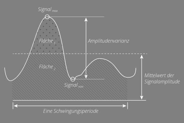
- Modulation Depth (MD) or Flicker percent – ratio of the difference and sum of the maximum and minimum light levels expressed as a percentage;
- Flicker Index (FI) - ratio of the areas above and below the average light levels.
However, these metrics do not distinguish between flicker and stroboscopic effect and do not account for the effect of frequency-dependent sensitivity or the wave shape of the light output. More sophisticated metrics are increasingly preferred:
- Short-term flicker severity, Pst LM (CIE TN006:2016) [1] assessment of perceived light flicker for frequencies up to 80Hz.
- Stroboscopic Visibility Measure, SVM (CIE TN006:2016) [1] considers effects on appearance of moving and rotating objects when illuminated with light modulation up to 2kHz.
- ASSIST Flicker Perception Metric, Mp (ASSIST Vol 11, Iss 3) [8] describes an objective method to assess the visual perception of flicker observed.
The European Commission´s Ecodesign Regulation for light sources and separate control gear [10] came into force on 1st September 2021. Also known as the Single Lighting Regulation (SLR), it was revised in February 2021 to include mandatory limits of PstLM < 1.0 for flicker and SVM < 0.9 for stroboscopic effects.
Flicker Meters
All of the above metrics (MD, FI, PstLM, SVM and Mp) are measured and reported by the BTS256-EF Spectral Light and Flicker meter , the PFL-200 BNC detector based meter. To assist SSL manufacturers with EMC Directive compliance (2004/108/EC), a turnkey Flicker Test System is available incorporating an objective flicker light meter in accordance with IEC TR 61547-1:2017 [9] for testing:
- the intrinsic performance of all lighting equipment with stabilised AC mains supply voltage;
- the immunity performance of lighting equipment against fluctuations in AC mains supply voltage.
The term ‘flicker’ is also used in connection with voltage fluctuations and resulting flicker on public mains-voltage systems caused by equipment connected to the network. IEC 61000‐3‐3: 2017 is concerned with the limitation of such voltage fluctuations produced by equipment. LED lamp luminaires ≤ 600W are “deemed to comply”.
References
[3] EN 12464-1:2011 Light and lighting. Lighting of work places. Indoor work places.
[4] NEMA 77: 2017. Standard for temporal light artifacts: Test methods and guidance for acceptance criteria
[5] ENERGY STAR Method of Measurement for Light Source Flicker
[6] CEC Title 24: 2016. Reference appendices: Appendix JA10 – Test Method for Measuring Flicker of Lighting Systems and Reporting Requirements.
[9] IEC TR 61547‐1:2015. Technical Report: Equipment for general lighting purposes – EMC immunity requirements – Part 1: An objective voltage fluctuation immunity test method.
Irradiance Measurement of High-Power UV Light Sources (UV Curing)
High intensity UV radiation is present in a range of applications. For example, high power UV light sources are widely used for UV curing which presents a number of measurement challenges that need to be addressed.
UV curing is a photochemical process in which polymerization is initiated when photoinitiators, mixed within the material, absorb high energy UV [1]. Controlling the exposure of work pieces to UV energy (time and intensity) is essential in the curing processes widely used for coating, printing, adhesives, encapsulants and potting compounds. To monitor and adjust the UV energy, the irradiance needs to be measured as close as possible to the surface of the irradiated parts in order to represent the same exposure. Successful curing requires the correct dose of UV at the wavelengths appropriate for the particular material. Dose, measured in J/cm², is the product of UV intensity and time of exposure (W/cm² x seconds). UV intensity (irradiance) is measured by a UV radiometer in W/cm², but may also be displayed directly as a dose in J/cm². A suitable radiometer must also be able to withstand a high temperature environment or have the option to offer correction for temperature effects. Since such radiometers allow exceptional performance for such high intensity applications, the technology is also used for UV lithography applications (see App. 038 UV measuring devcies for mask aligners (lithography)).
There are two main types of UV source used to generate the needed high-intensity UV-irradiation:
1. High-Power Gas Discharge Lamps (e.g. medium pressure mercury lamps): These gas discharge lamps produce intense UV radiation by vaporizing the mercury into an extremely high-temperature plasma gas within a sealed quartz tube containing an inert gas mixture. The spectral composition can be modified to some degree by adding dopant metals such as iron or gallium. The emitted light is very well defined regarding its spectral peaks due to inner atomic transitions with defined energies. In addition to the UV radiation, gas discharge lamps also produce very high levels of IR radiation from the quartz envelope of the lamp, which may be either a help or a hindrance to the successful hardening of materials.
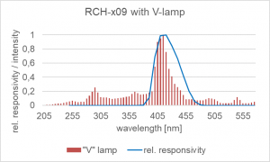
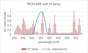
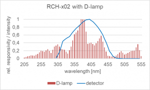
2. High-Power UV-LEDs (e.g. at 365 nm): In recent years, the trend has clearly been toward using high-power LEDs as light sources. With the most recent developments, they offer increasing UV outputs as well as the benefits of instant switch on and the resulting energy efficiency. Combined with the stability as well as life time advantages [2] LEDs are now at a very competitive level and will continue to improve. However, other topics such as the wavelength stability due to heating effects have to be considered. Since the absorption within the curing material is also closely related to the wavelength of the irradiation, deviations here can lead to changes of the curing process and its duration. Dose monitoring due to life time restrictions is of course still an important task. As mentioned, LEDs have significantly improved for UV applications, but aging is a significant effect [3]. 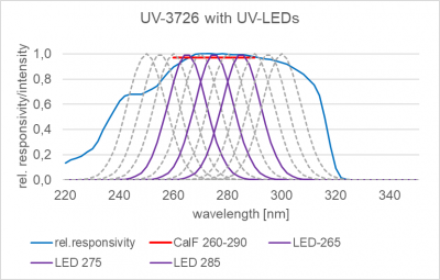
An important fact: The output intensity of both gas discharge lamps and LEDs degrades over time. Therefore, to ensure the required dose is achieved, irradiance should be closely monitored. Using this information, process times can be adjusted to ensure the UV-curing process within the material is completed. Lamp replacement schedules can also be optimized based on such radiometric measurements.
Therefore, the selection of radiometers suitable for UV curing measurement employing high intensity gas discharge lamps as well as LEDs requires the following criteria to be met:
- Detector design for minimal ageing and drift when exposed to intense UV and heat radiation
- Cosine field-of-view detector (small f2) for high accuracy of irradiance measurements
- Flat-type detector enabling measurement plane to match that of the work piece surface
- Spectral responsivity of the detectors matched to the spectral sensitivity of the photo-initiators and the emission spectrum of the gas discharge lamp as well as LEDs
- Easy handling of the measuring device
- Protection of the user from the risk of intense UV and heat radiation
- Fast recalibration service and traceable calibration with options for ISO 17025 calibration and testing
Gigahertz-Optik offers different UV-curing measurement solutions which fulfill these requirements.
RCH-xxx Series: High Temperature Detector Series for Different Light Sources
For radiometric measurements in W/cm² and J/cm² (integral measurements), the RCH-xxx Series detector heads from Gigahertz Optik GmbH are most suitable. The innovative design of these proven measurement heads ensures that the sensitive photodetector is both thermally isolated and protected from the high UV levels present. With this concept, the RCH-Series has been meeting the high demands of radiation curing for many years with attractive price. Different versions for different light sources are available.
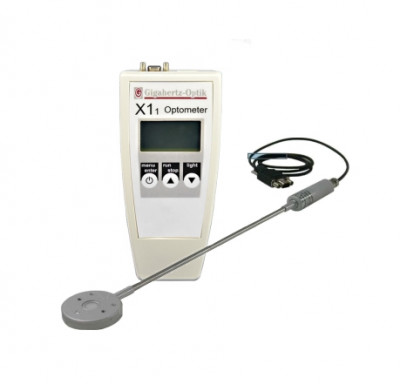
Cure-Met: An UV-Curing Disc
Gigahertz-Optik also transferred its knowledge for integral measurements into the Cure-Met, a UV-Curing disk. It offers the possibility to be placed on conveyor belts in order to run though larger curing setups. Here it continuously logs data in the internal storage to offer a local irradiance profile.
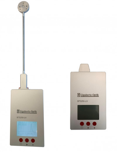
BTS256-UV: A superb Spectroradiometer for UV Curing Applications
A different solution is our BTS256-UV series of spectroradiometers. It offers not only an integral measurement, but also spectral details in addition. Particularly useful for LED-based light sources, this offers new opportunities to e.g. monitor the wavelength as well as to perform binning when selecting suitable LEDs.
Calibration
For any kind of radiometric irradiance measurement, calibration of the detector is a very critical parameter for the accuracy of the final measurement result. An underestimated topic for the integral measurements is the spectral mismatch and its correction to measure different light sources with high accuracy respectively low measurement uncertainty (see App. 020 Reduced Measurement Uncertainty for UV-A, UV-B and UV-C Radiometers ). In other words, a low calibration uncertainty which you can trust is important. In that respect we offer calibrations from our DAkkS ISO 17025 accredited calibration and testing laboratory. This means highest standards according to the ISO 17025 are applied to the processes to ensure reliability and traceability of our calibrations. All calibrations are directly traceable to the PTB, the German NMI, or comparable NMIs. Our calibration laboratory covers the wavelength range from 200 nm – 2500 nm and a variety of optical measurands.
References
[1] Photoinitiators for UV and visible curing of coatings: Mechanisms and properties
[2] Lifetime Analysis of Commercial 3 W UV-A LED
[3] Degradation of external quantum efficiency of AlGaN UV LEDs grown by hydride vapor phase epitaxy
LED
BTS256-E
UV
/assets/Uploads/BTS256-UV-Series-icon.jpg
UV radiometer for mask aligners (lithography)
A mask aligner is a precision machine tool used in the semiconductor manufacturing process to transfer a pattern onto a wafer or substrate; these patterns are micro and nano in scale. The patterns (structure) are created using a shadow transfer method, where the pattern (photomask) to be printed is placed between a light source and the substrate to be patterned (wafer). The substrate being patterned is first coated with a photosensitive material (photoresist), this material then reacts to the light projected from the shadow image. The resultant pattern is then developed using specific chemicals.
This process is commonly known as photolithography, more details of this micro-fabrication technique are covered in a separate document Lithography Basics [1].
Mask aligners enable photolithography to be used to produce semiconductor devices, such transistors, sensors and medical components, etc. Along with a method to uniformly coat the substrate with photoresist, a mask aligner is crucial to the photolithography process. A mask aligner is used to both precisely align the coated substrate to the photomask containing the structure to be patterned, and for then exposing the substrate with light to transfer the desired pattern onto the substrate.In applications where the light detector is susceptible to changes in temperature, as in a UV mask aligner used in semiconductor photolithography, the light detector temperature coefficient must be considered as a possible error source. Many current mask aligners employ a powerful mercury (Hg) lamp emitting high levels of UV that exposes the photosensitive material (photoresist) on the substrate. Dependent upon the photoresist used, the light should be transmitted in either the broadband range, or in a specific spectrum G: 436 nm, H: 405 nm or I: 365 nm.
An alternate option gaining favor to the mercury lamp is to use a UV LED array. These contain a number of LEDs that emit light at the G, H or I line wave-lengths, or a combination of all three to produce a similar broadband spectrum to that of the mercury bulb. (inseto-What Is A Mask Aligner)
Gigahertz Optik GmbH manufactures many differently configured UV filter radiometers for classical spectral broadband UV lamps such as medium & high pressure mercury vapor lamps or low-pressure lamps found in mask aligners. These radiometers have been developed in coordination with our customers that manufacture mask aligners and other photolithography apparatus. Often this results in us becoming an OEM supplier with private label business arrangements. We offer unique customized solutions like temperature correction function built-into the electronics that measures the temperature and corrects the irradiance reading accordingly.
We also offer UV radiometers for measuring the irradiance at different LED wavelengths and spectroradiometers which provide wavelength as well as intensity information. The advantages of UV filter radiometers include a favorable price/performance ratio, a flat low profile detector design as required, fast measurement times and robustness. Spectroradiometers are not restricted to a specific spectral bandpass so they are more versatile and useful especially in research use.
• BTS256-UV Cordless Flat Spectral Radiometer - Four Models of Input Optic
• RCH-XXX Series UV Curing Detectors for High Temp & UV Irradiance
• PLCD Detector/Amplifiers - Customer configured - (4-20) mA or (0-20) mA for PLC
• MDC-4-UV-BLUE Smart Integral Detector for LEDs with Wavelength Detection
We offer UV radiometers with filter-corrected detectors for classical spectral broadband UV lamps such as medium-pressure mercury vapor lamps or low-pressure lamps at mask aligners. Here we rely on decades of experience with major customers in this field. Often we also act as OEM supplier with customer logo. Due to the increasing use of LED light sources, we also offer UV radiometers for measuring the irradiance of different LED wavelengths as well as spectral measuring systems (spectroradiometers). The advantage of UV radiometers results from their favorable price-performance ratio, the flat design, the short measuring times and their robustness. Spectroradiometer measurements are largely independent of the LED's spectral range. We would be happy to work with you to find the best solution for you, and we are also happy to support OEM labels.
References
LED-MSC15
/assets/Uploads/LandingpageHeader_BTS256.png
UV Preconditioning Tests of PV Modules according to IEC 61215 Series
The qualification of PV modules according to IEC 61215 and IEC 61646 requires preconditioning with defined doses of UVA and UVB radiation. Unlike conventional radiometers, the BTS256-UV spectroradiometer enables the most accurate measurement of UVA and UVB irradiance levels irrespective of the type of UV source used. Each device is supplied with a traceable calibration certificate and is designed to operate at the required high temperature.
The BTS256-UV measures the spectral irradiance produced by UV preconditioning systems over the spectral range 280 nm to 400 nm. This enables the most accurate determination of the absolute proportions of UVA and UVB radiation. Incorporation within automated systems is made possible via the RS-485 serial interface with the software Read-out Kit, S-SRK-BTS256. This enables control of the UV radiation system and ensures an appropriate dose of UVB radiation within a total UV prescribed dose of 15 kWh/m2. The full measurement data are available via the user application software or the Read-out Kit.
The BTS256-UV spectroradiometer is built into a stainless steel housing that has excellent UV stability and low thermal conductivity providing reliable operation at the obligatory temperature of (60±5)°C. Its thin construction and integrated cosine diffuser ensure correct measurement of irradiance in the required plane.
The calibration laboratory at Gigahertz-Optik offers factory calibrations for the BTS256-UV with the highest level of traceability. They are subject to the same quality management as used in Gigahertz-Optik’s DAkkS-accredited calibration and testing laboratory. ISO 17025 accredited test certificates of calibration for the BTS256-UV are optionally available.
The BTS256-UV spectroradiometer covers the spectral range 200 nm to 520 nm and is therefore suitable for other high intensity UV applications including UV curing, solar simulation, UV weathering systems, and germicidal UV radiation
The qualification of PV modules according to IEC 61215 and IEC 61646 requires preconditioning with defined doses of UVA and UVB radiation. Unlike conventional radiometers, the BTS256-UV spectroradiometer enables the most accurate measurement of UVA and UVB irradiance levels irrespective of the type of UV source used. Each device is supplied with a traceable calibration certificate and is designed to operate at the required high temperature.
Gigahertz-Optik BTS256-EF light meter for the qualification of nautical navigation lights at OPTONAVAL